The Raspberry Pi is a compact, powerful and affordable single-board computer employed by hobbyist and professionals alike in a wide variety of projects. We’ll be making use of the Raspberry Pi’s GPIO (General Purpose Input and Output) pins to trigger external devices (such as Relays, Microcontrollers, PLCs, etc. ) straight from the Lensmaster timeline.

GPIO Pins
These pins can be controlled programmatically. We’ll be using them to interface with Relays and other devices.
These pins can be controlled programmatically. We’ll be using them to interface with Relays and other devices.
Ethernet Port
We’ll be using this ethernet port to connect the raspberry PI to the same network switch as the Robot and computer running Lensmaster.
We’ll be using this ethernet port to connect the raspberry PI to the same network switch as the Robot and computer running Lensmaster.
USB type A 3.0 Ports
USB type A 2.0 Ports
USB Type C
This port is used to power the Raspberry PI using a USB-C power adapter.
This port is used to power the Raspberry PI using a USB-C power adapter.
Micro HDMI ports
MicroSD Port
Insert your MicroSD card with Raspberry Pi OS here.
Insert your MicroSD card with Raspberry Pi OS here.
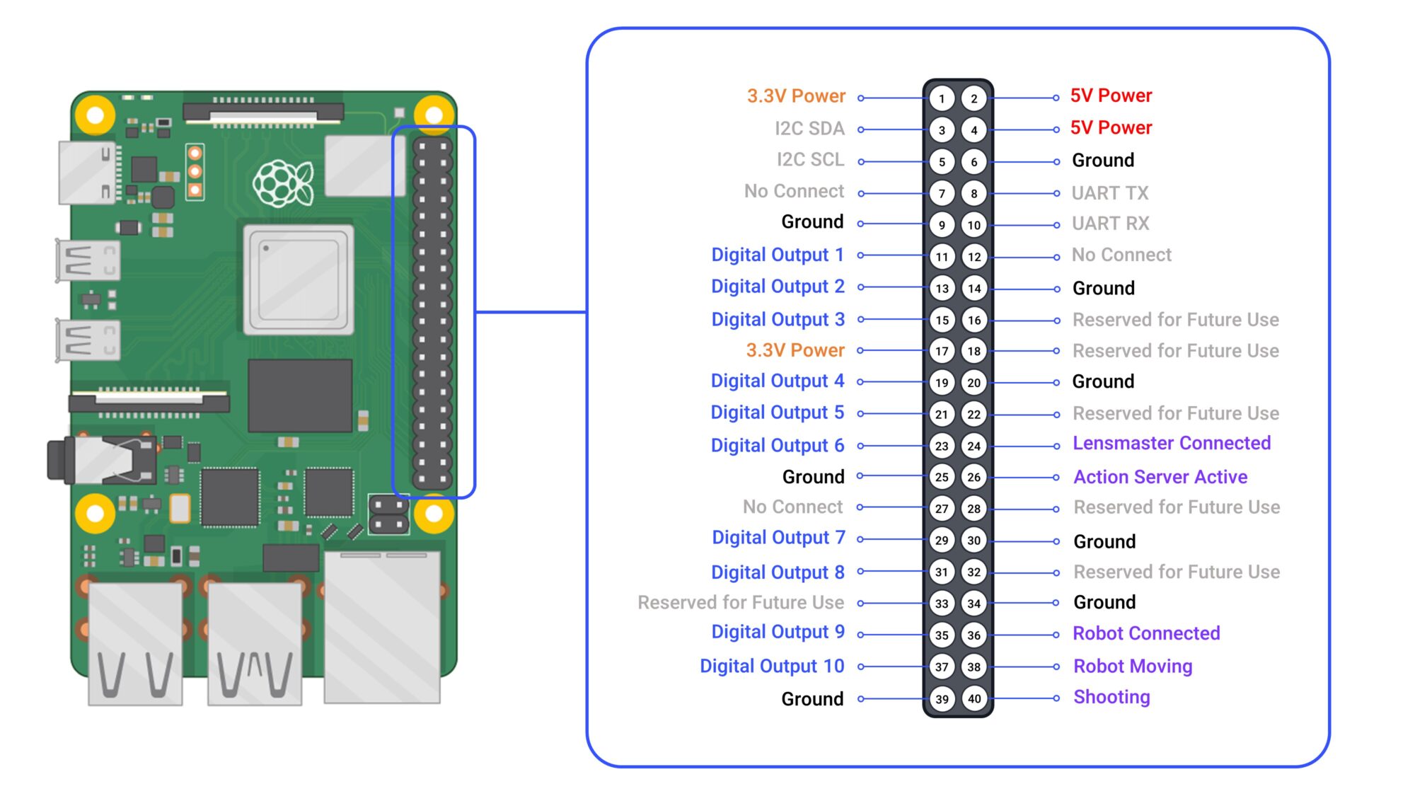
Action Server Pinout
Tip: Click the image to enlarge it
Digital Outputs 1-10
These output pins can be toggled Active or Inactive (and pulsed) in sync with the robot using the Lensmaster Timeline. They can also be manually controlled from the Trigger Action Properties panel.
Lensmaster Connected
This pin goes ACTIVE whenever the Action Server is connected to Lensmaster.
Action Server Active
This pin goes ACTIVE when the action server is powered on and running nominally.
Robot Connected
This pin goes ACTIVE whenever the Robot is connected to Lensmaster. We recommend connecting it to an Indicator Light through a relay to inform everyone on set that the robot is engaged.
Robot Moving
This pin goes ACTIVE whenever the Robot is connected to Lensmaster and moving (Timeline Playback, Jogging, GetReady, etc.). We recommend connecting it to an Indicator Light through a relay to inform everyone on set to stay clear of the robot.
Shooting
This pin goes ACTIVE whenever the timeline is Shooting (Even if the robot is not connected). This can be used to trigger actions at the start of the move such as the Camera recording or an external motion control system.
The ACTIVE state of the GPIO pins is by default LOW (0V). It can be changed to ACTIVE HIGH (3.3V) by setting “active_low” to “false” in the “config.json” file inside the “LensmasterActionServer” folder on your Raspberry Pi.
The Raspberry Pi GPIO pins operate in the 0V to 3.3V range and can only handle a maximum current of 16mA each. As such we highly recommend not powering any devices directly through the GPIO pins and instead using Relays, Transistors or other switching devices, capable of handling the controlled device’s power requirements.
Sample Wiring Configuration
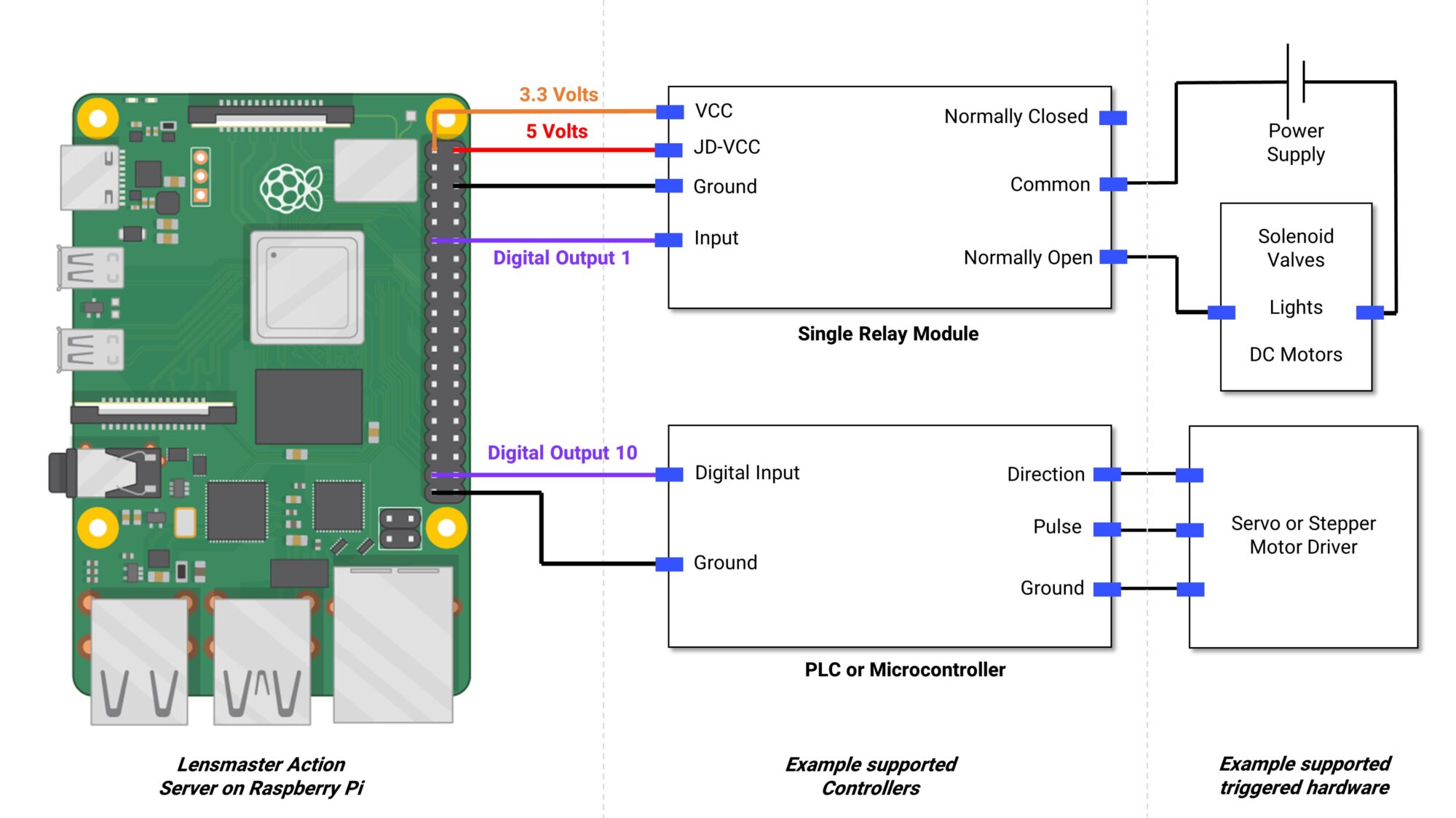
Tip: Click the image to enlarge it